Marine Air Conditioning System Diagram
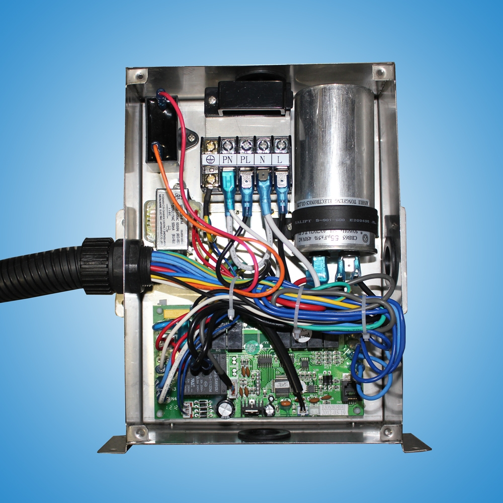
Marine air conditioning system diagram. Wires labeled Main Power In must be connected to the main power in terminal on the unit. Use with direct expansion reverse cycle air conditioning systems. The cause is likely air in the system.
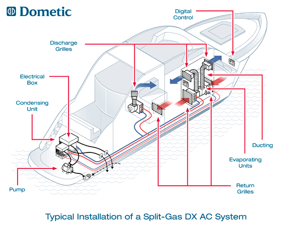
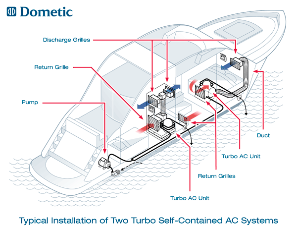
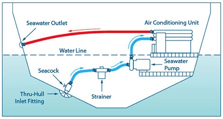
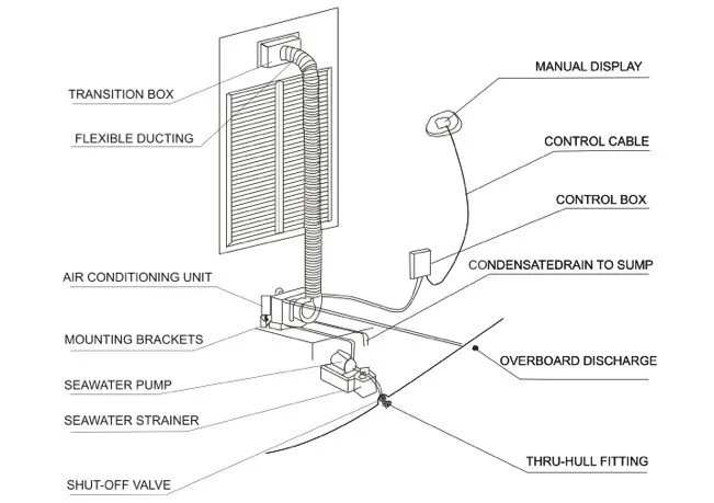
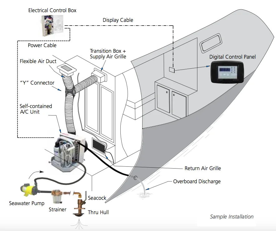
Cooling water is provided to the air conditioner via a foot scoop sea cock water strainer and pump as-sembly all of which are mounted below sea level. The warm air thats pulled in from the cabin is called return air while the supply air is the cold air coming out of the air handler. The air should be discharged high in the cabin and away from the return air grill to.
Efficient heat exchange at the evaporator demands a free. Grille louvers should be directed upward. The return air grille should be installed as low and close to the ac as possible to insure direct uninterrupted airflow to the evaporator.
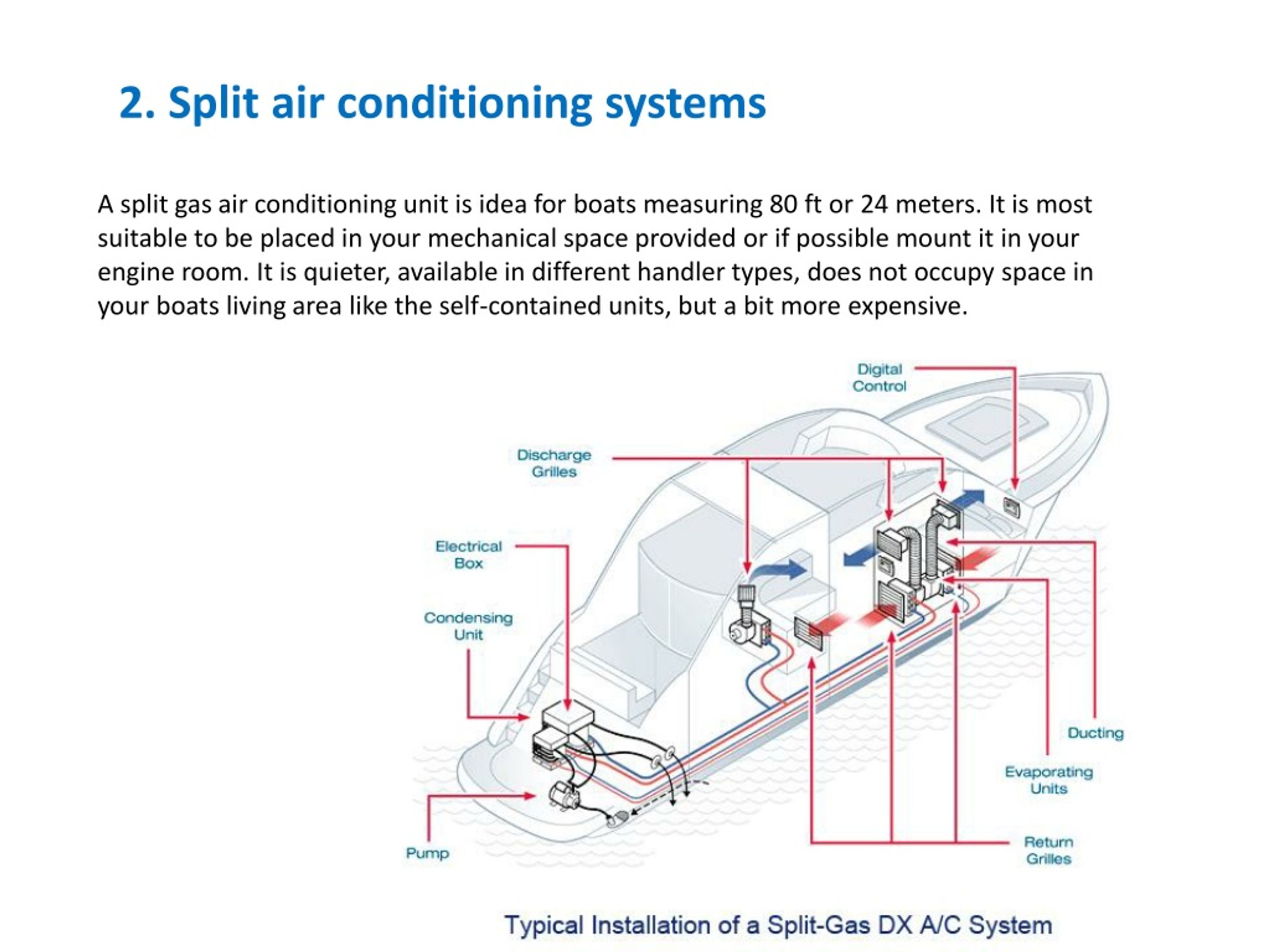
Air Distribution System Cabin air is drawn into the self-contained unit or coolingheat-ing unit through a return air grill. In a typical Split-Air set-up 1 2 or 3 Split-. Air Handler Wiring Diagrams.
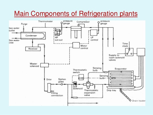
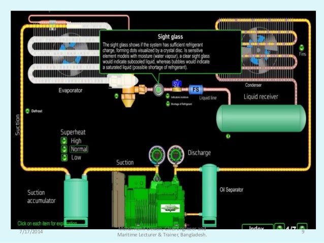
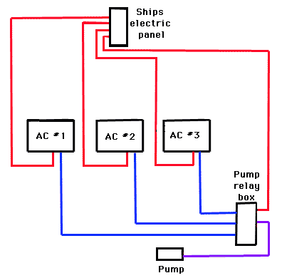
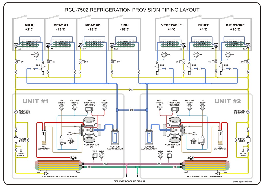
The refrigeration plants on merchant vessels play a vital part in carrying refrigerated cargo and provisions for the crew on board. We are showing the wiring to connect our units as well as the pumps on our line of self contained units. Clogged air conditioning condenser coils can make your boat unbearably hot.
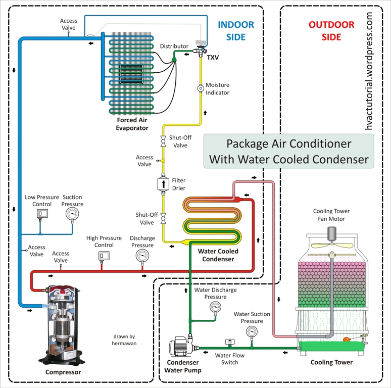
Return-air grille mounted as low and as close to the unit as possible. Supply-air grille mounted as high as possible. The component at 2 in this air conditioning circuit and cycle diagram is the condenser.
5The air conditioning unit must be mounted to a low flat level surface like in the bottom of a locker under a bunk or dinette seat or in a similar location. The Replacement Cruisair Compressor used in F and R series units are also available for Btu.
Up to 167k 200k and above.
The refrigeration plants on merchant vessels play a vital part in carrying refrigerated cargo and provisions for the crew on board. 5The air conditioning unit must be mounted to a low flat level surface like in the bottom of a locker under a bunk or dinette seat or in a similar location. 10K 12K and 16K - 115v and 230v. Return-air grille mounted as low and as close to the unit as possible. The red dots inside the piping represent discharge vapor. All central marine air conditioning and heating units are water cooled. The thru-hull allows your boats AC unit to draw raw water from the sea. We are showing the wiring to connect our units as well as the pumps on our line of self contained units. And the operating pressures will depend on the refrigerant being used and the desired evaporator temperature.
DCU18K 230V60HZ 410A PN 205600819 The Vector Compact series of self-contained marine air conditioners offers 18000 and 27000 and 30000 BTUhr of reverse-cycle cooling and heating. If this is the problem clean the system for improved airflow. 2175 NW 34th Ave Miami FL 33142 USA Phone. The same plant or a smaller unit can be. It is then cooled or warmed and blown back into the cabin through a ducting system. Standard Features Universal 115230 volt 5060 Hz AC power supply. For boats that are in dry storage you may install a T fitting at the discharge of the pump with one line running to a vertical location with a valve for releasing the back pressure to simplify priming.
















Post a Comment for "Marine Air Conditioning System Diagram"